Make your DIY Sim Racing Handbrake
Here I will explain to you how to build a DIY Sim Racing Handbrake. This Handbrake is easy to build, has a strong structure, stable and smooth mechanism.
There is almost no difference between the 3D printed version and the metal version (laser cut or CNC). The assembly will be almost the same. You can use this tutorial if you have opted for a steel/aluminium handbrake.
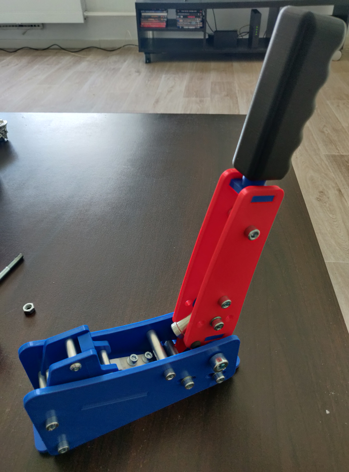
Here is what I will help you achieve:

First step, you need to look at this video :
REQUIRED PARTS
The Screws :

| Diameter x Length – Screws | Quantity |
| M8 x 40 | 1 |
| M6 x 40 | 1 |
| M6 x 10 | 10 |
| M8 x 130 Semi-threated (socket cap smooth) | 1 |
| M10 x 60 | 1 |
| M6 x 16 | 8 |
| M6 x 10 button head | 2 |
| M5 x 30 | 2 |
| M4 x 30 | 2 |
| M5 x 10 button head | 6 |
| Diameter x Length – Nuts | Quantity |
| M8 Lock Nut | 1 |
| M6 Lock Nut | 1 |
| M10 Lock Nut | 1 |
| M5 Lock Nut | 2 |
| M4 Lock Nut | 2 |
| Diameter x Length – Washers | |
| M6 | 10 |
| M10 | 1 |
| M5 | 2 |
| M4 | 2 |
| Diameter x Length – Spacers | Quantity |
| M6 x 20 | 3 |
| M6 x 40 | 5 |
| M5 x 20 | 3 |
Here are the other parts required :
- 20kg Loadcell [Option : 1pc 20kg sensor]
- Recommanded Spring [Option: Length: 65mm, Diameter: 20mm]
- M8 Female Rod end [Quantity: 1] [Option: PHS8 Right thread]
The 3D Printed Parts :

Spring, Loadcell, Female Rodend

STEP 1 : The mobile part
To begin, we will assemble the mobile part.
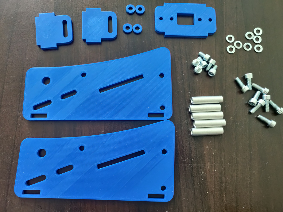
The required parts:
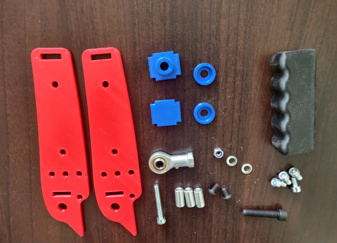
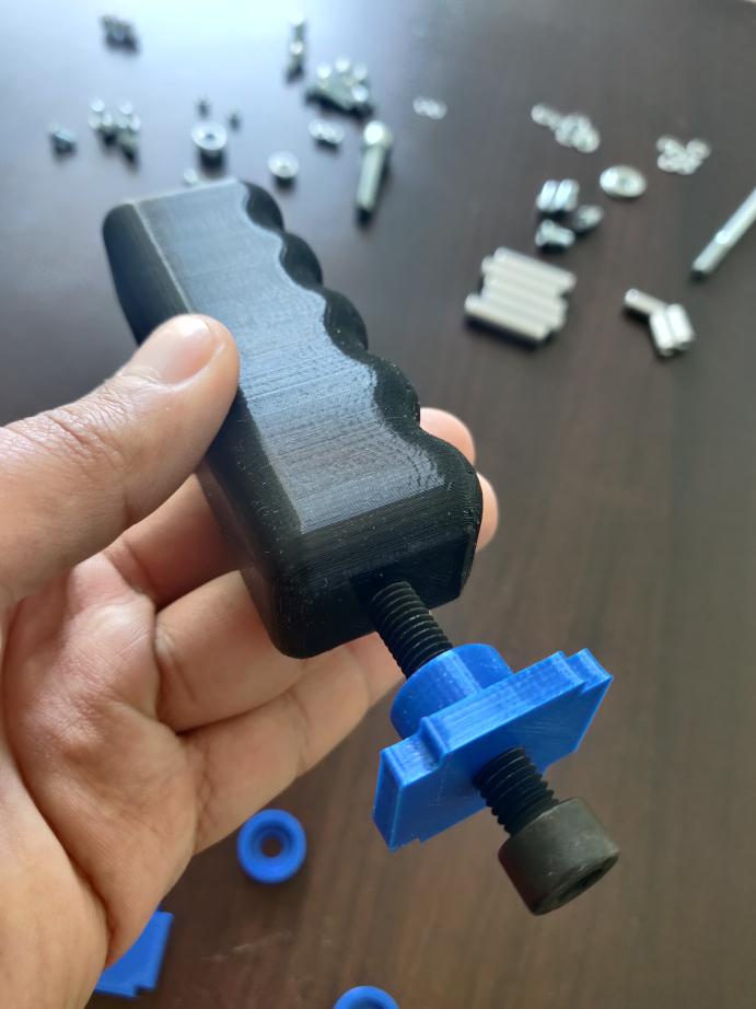
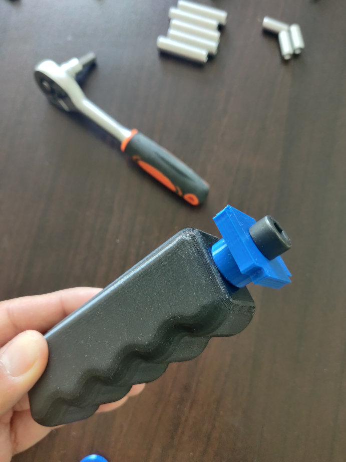
Assemble the handle and its support by screwing it.
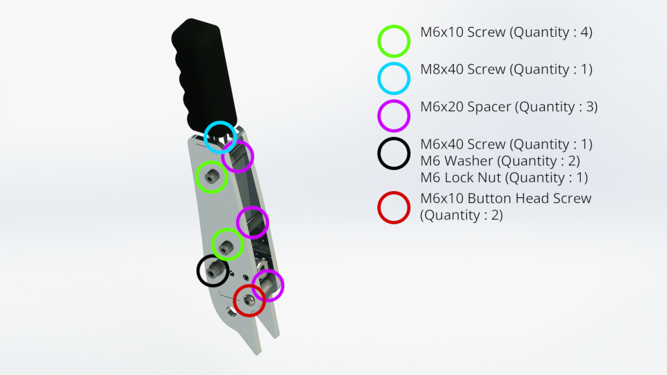
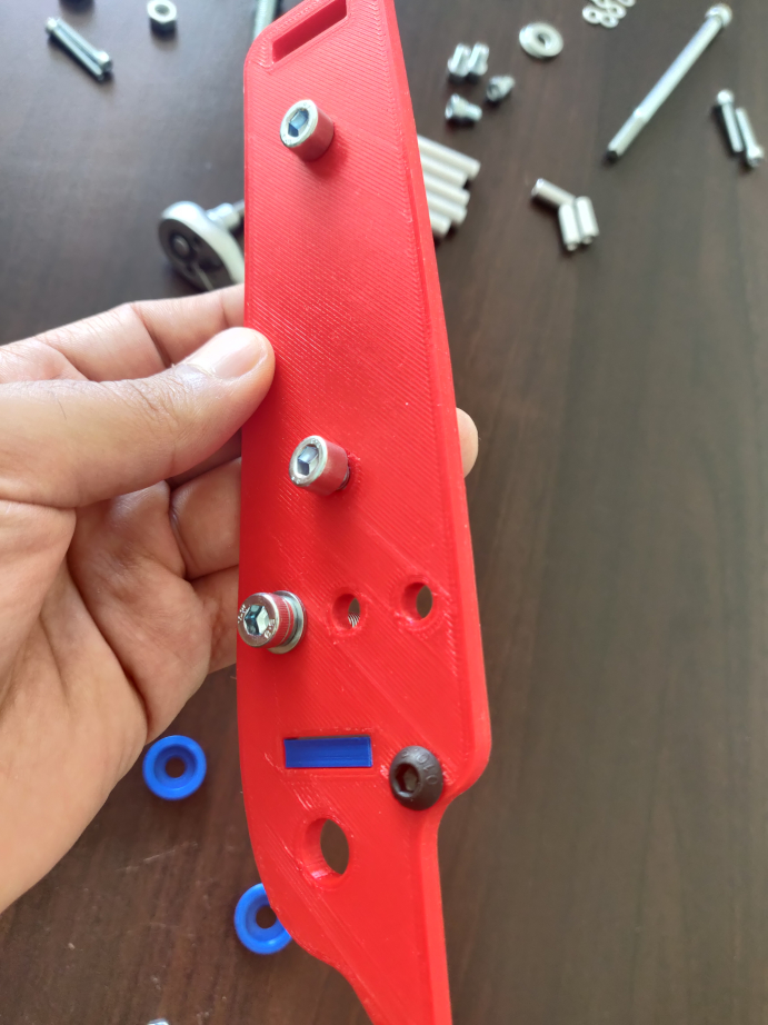
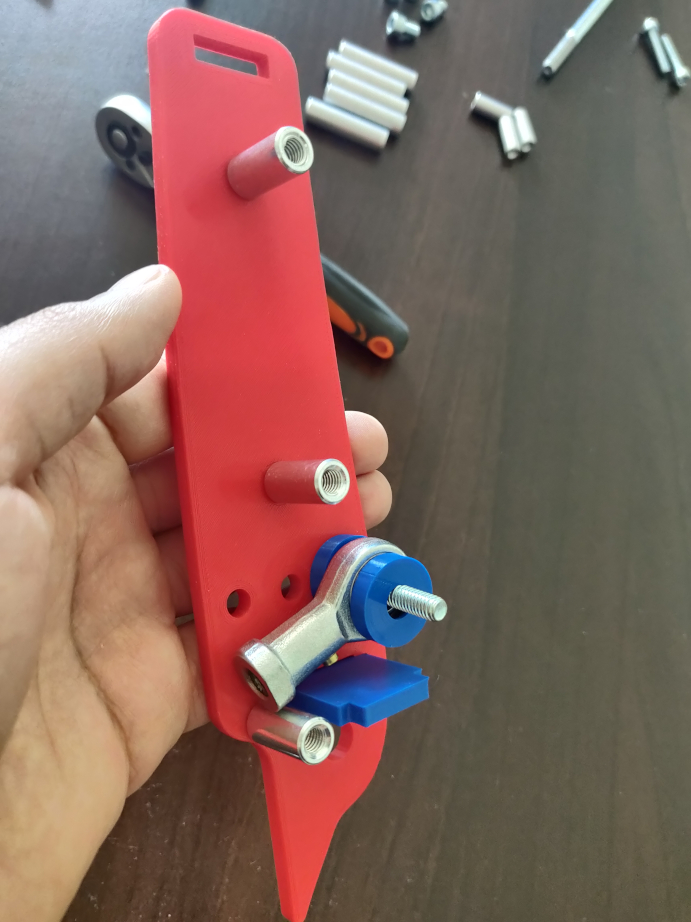
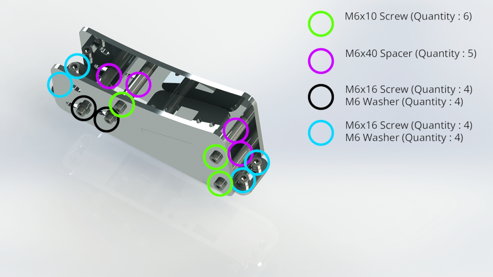
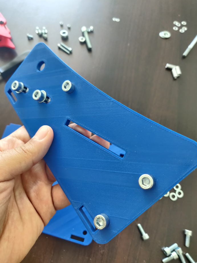
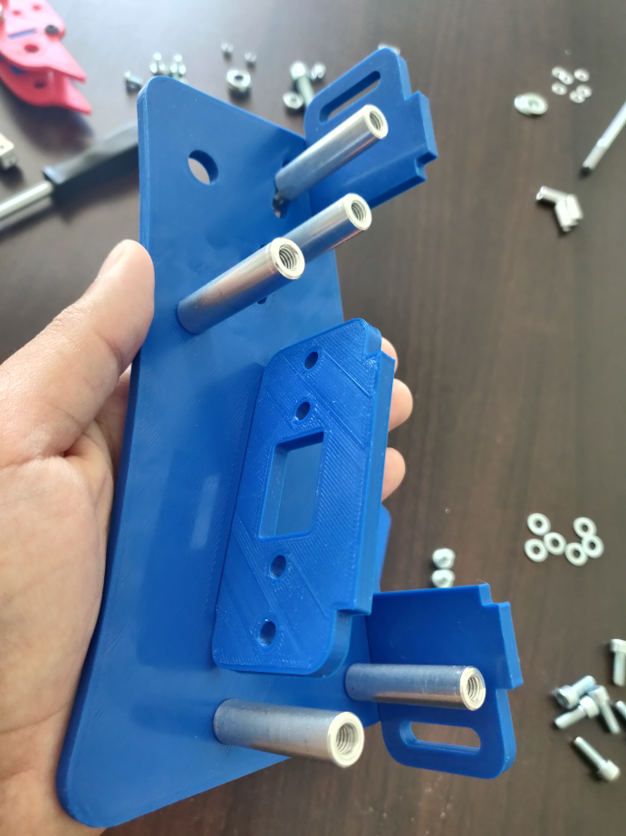
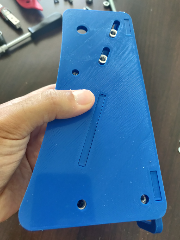
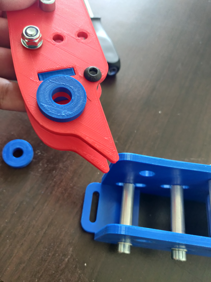
Next, assemble the first plate. You must insert the screws and spacers, after that the bottom mortise, M8 Female rodend and its centralizers (blue in the photos).
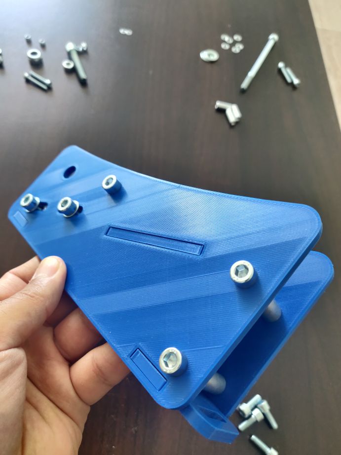
Mount the second plate without forgetting the handle.
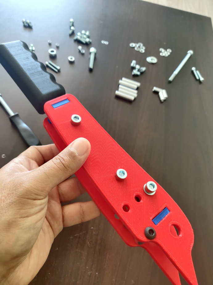
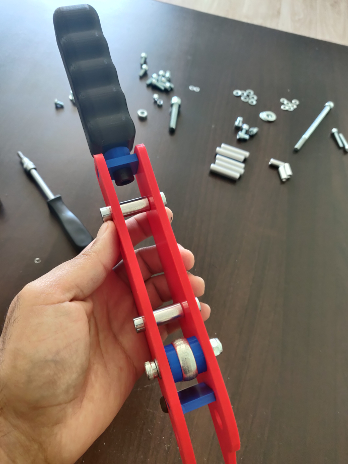
Your mobile part is assembled.
STEP 2 : The fixed part
The required parts :
Like the mobile part, you must start by mounting the first plate.
Then, mount the second plate.
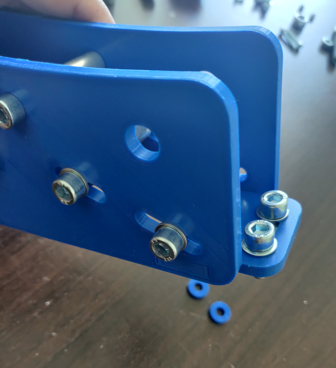
When you mount your handbrake on your cockpit, you must use the M6x16 screws and the blue spacers.
Your fixed and mobile part is assembled, we will now assemble the loadcell part.
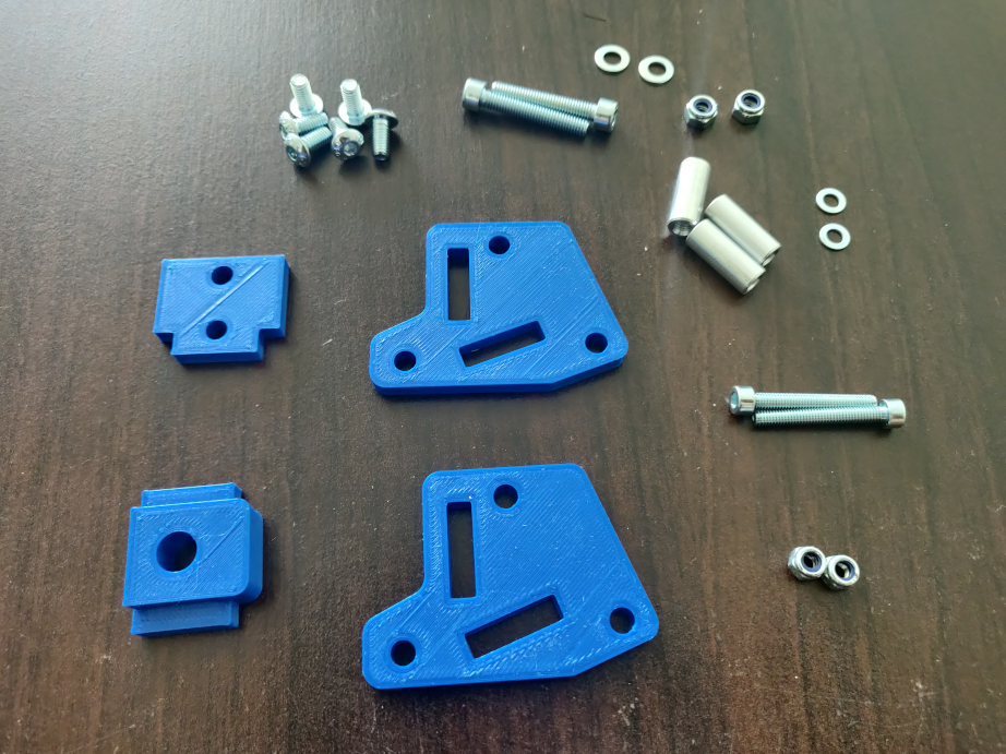
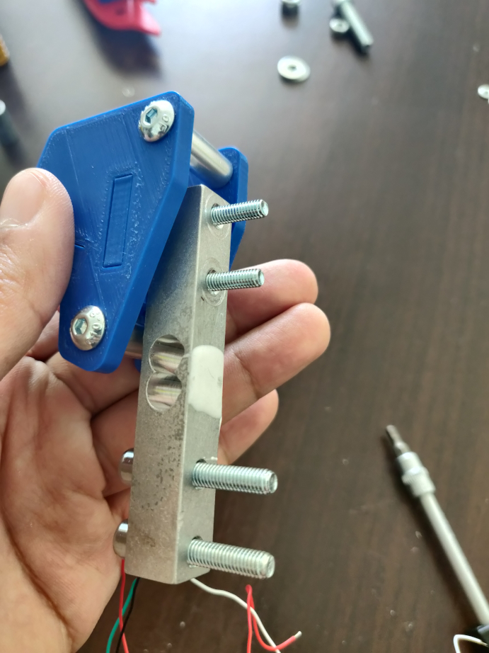
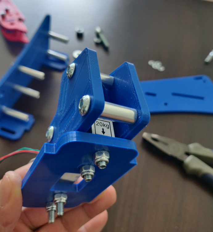
STEP 3 : The loadcell part
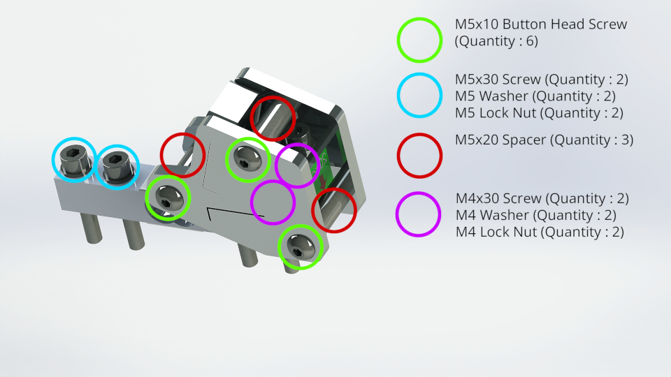
The required parts :
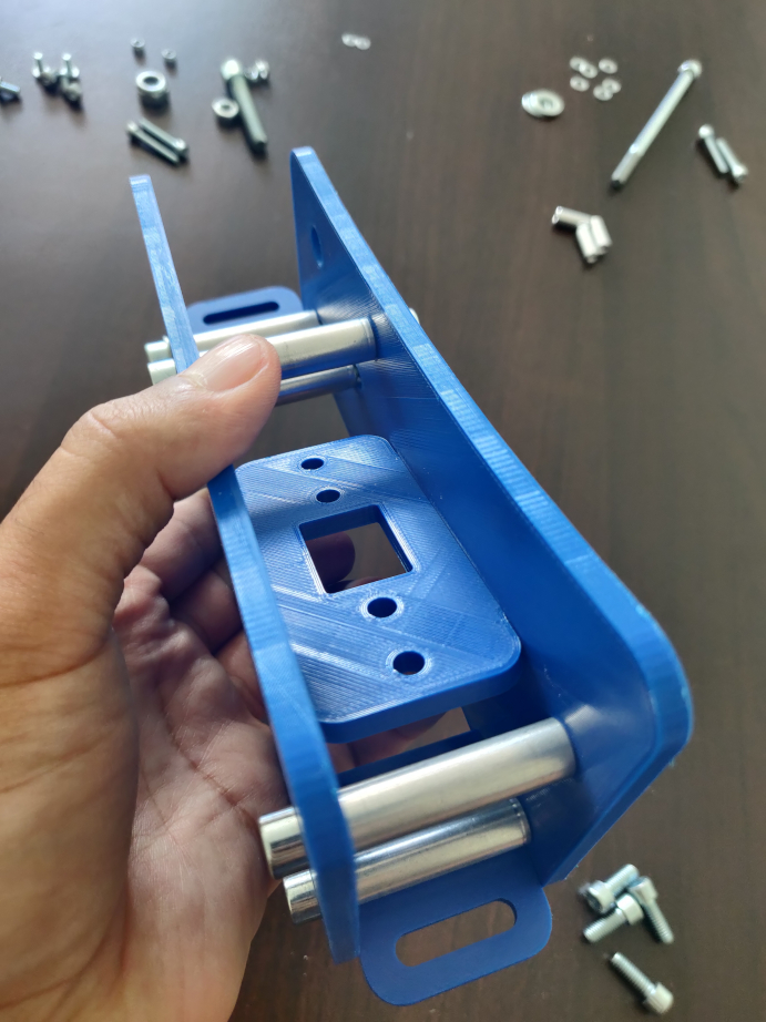
To start, here is a photo of the structure of the loadcell part :
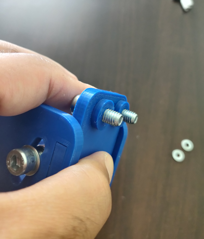
You can start by mounting your loadcell with the screws/washers (except the nuts).
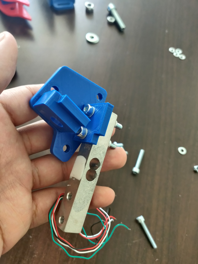
Then, finish assembling.
You can now screw in the last two bolts.
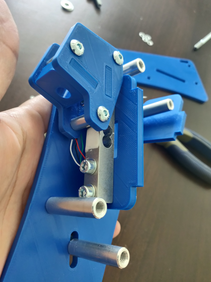
We must now fix the loadcell on the the fixed part.
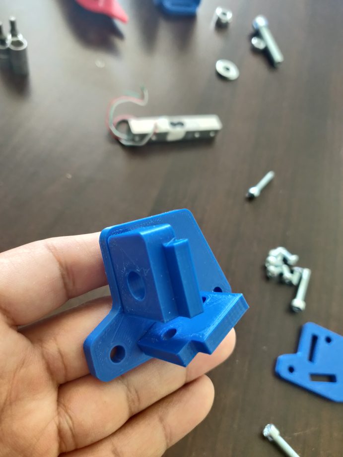
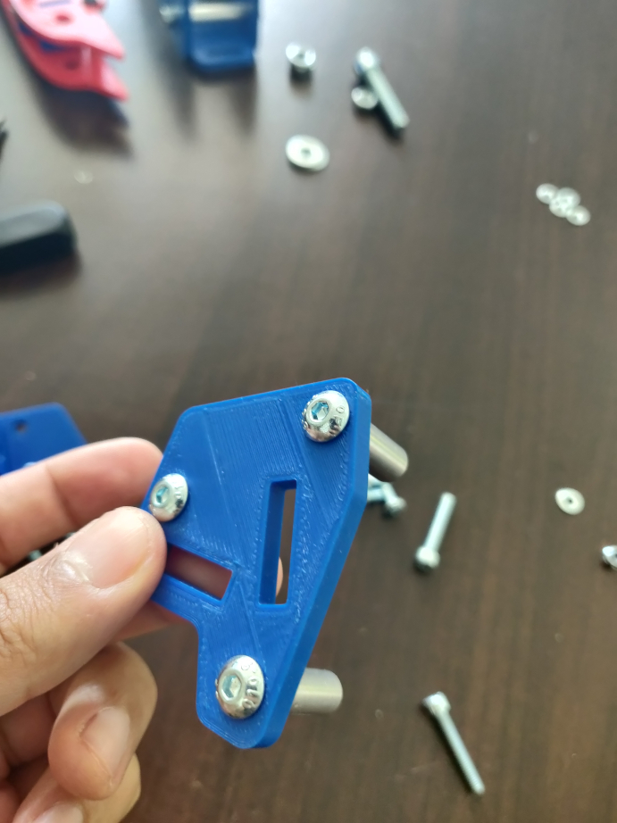
You must first remove a plate from the fixed part. Then, attach the loadcell to the loadcell support plate (with 4 holes and a rectangle in the middle) which is removed in this photo :
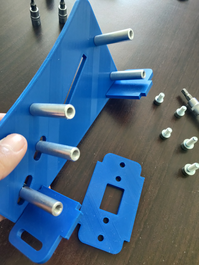
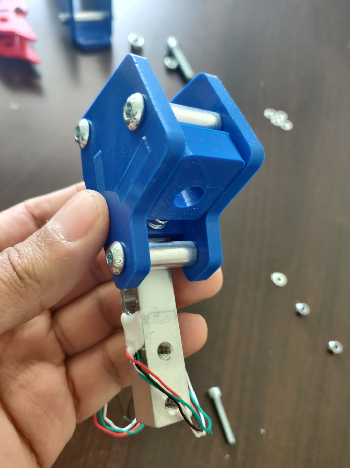
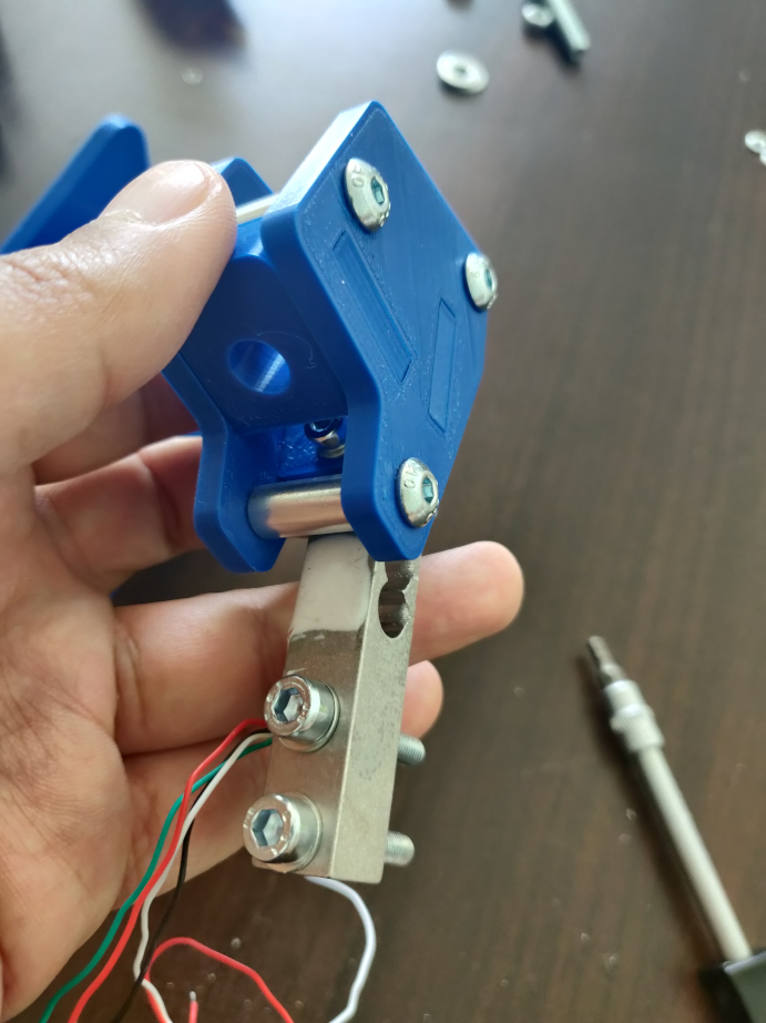
Mount the loadcell on the loadcell support plate :
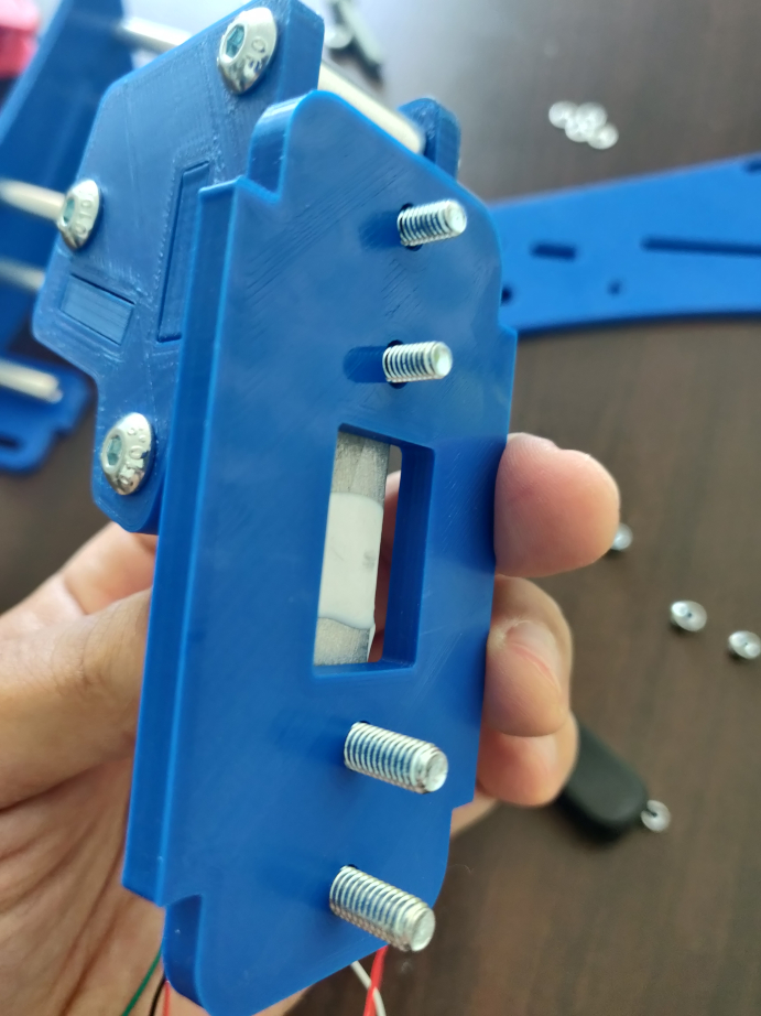
And now, mount it all in the fixed part.
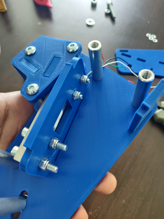
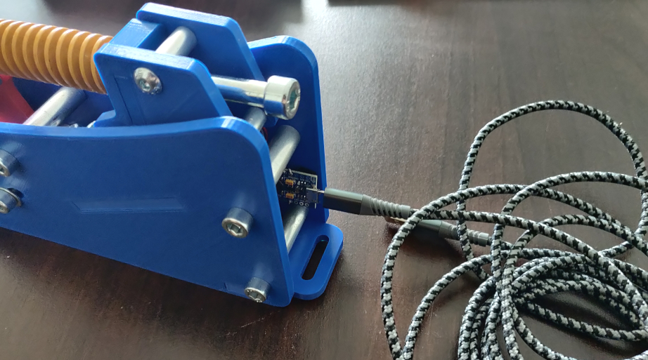
Be careful with the loadcell wires, they are quite thin and fragile, avoid damaging them or pulling them.
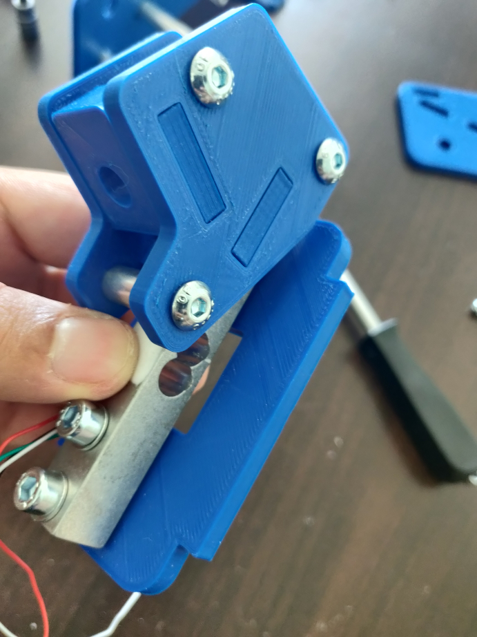
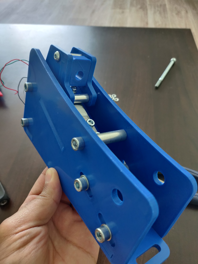
STEP 4 : The final assembly
We are going to assemble the fixed part and the mobile part.
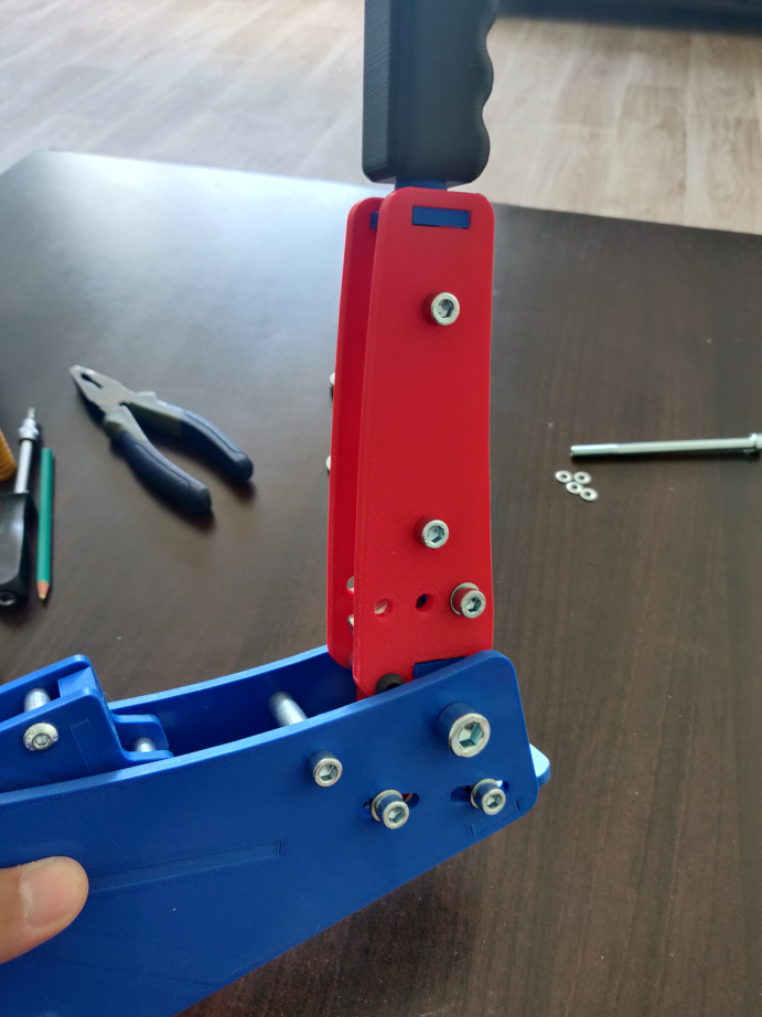
Also, remember to adjust the tightness of the M10 lock nut screw to avoid any lateral play on the mobile part.
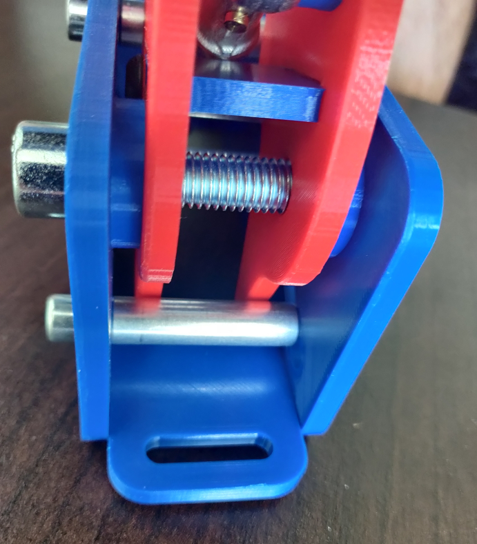
Finally, you need to assemble the spring and the M8x130 screw.
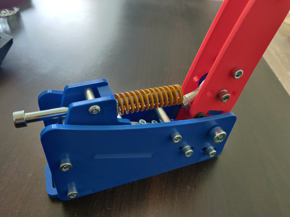
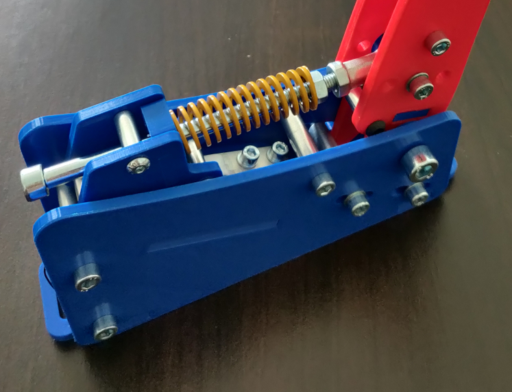
You can also use an elastomer if you wish, but in my case I will only use this yellow spring.
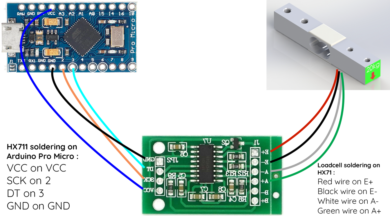
STEP 5 : Soldering
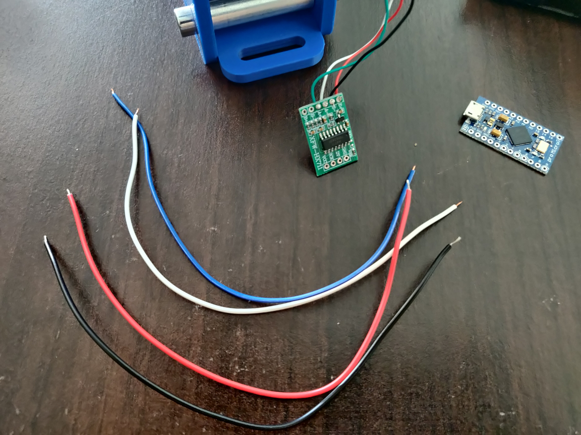
You have now completed the assembly, you need to move on to soldering. We will use the Arduino Pro Micro USB board and the HX711 amplifier.
Here is the soldering diagram:
The Arduino Sketch is provided in the file.
- Arduino Pro Micro Board
- HX711 Board (option: Standard Board)
- Micro USB Cable
- Arduino software: https://www.arduino.cc/en/software
- Joystick library (mandatory): https://github.com/MHeironimus/Arduin…
- HX711 library (mandatory): https://github.com/bogde/HX711
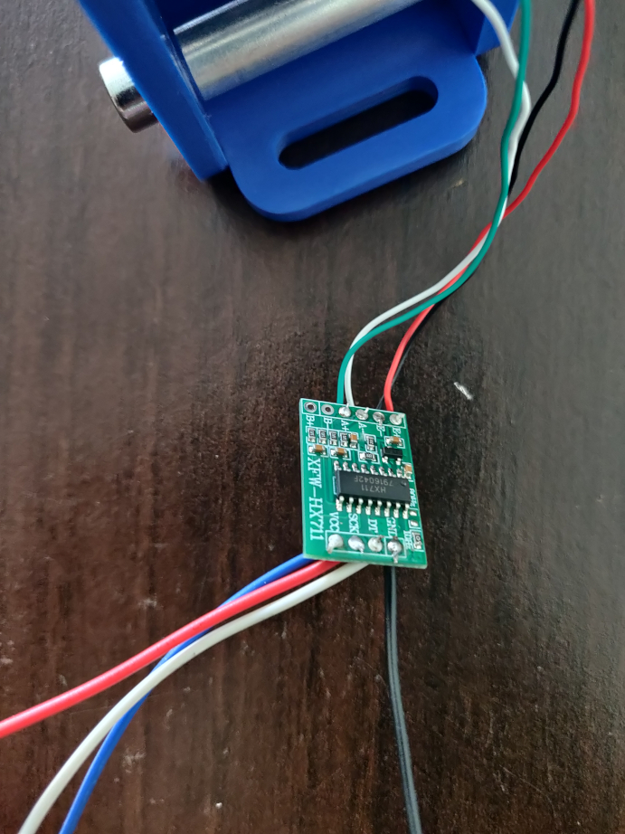
To start, you have to solder the loadcell wires on the HX711 card. I used this Electric Soldering Iron.
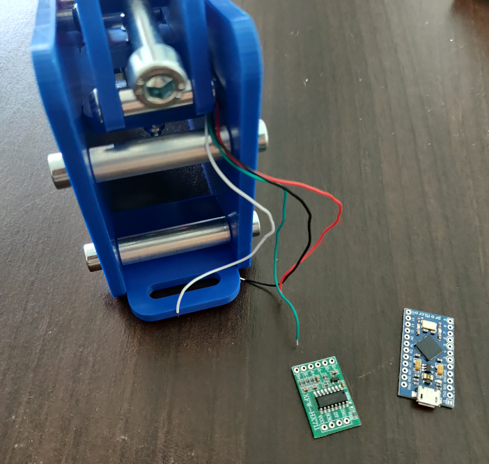
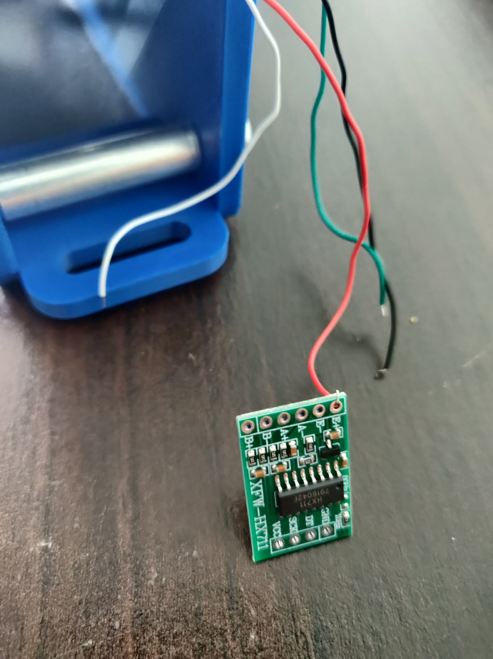
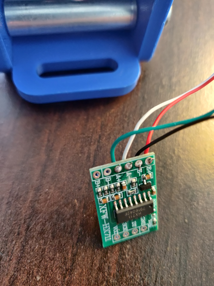
Then, you must connect the HX711 board to the Arduino board. You will need 4 wires.
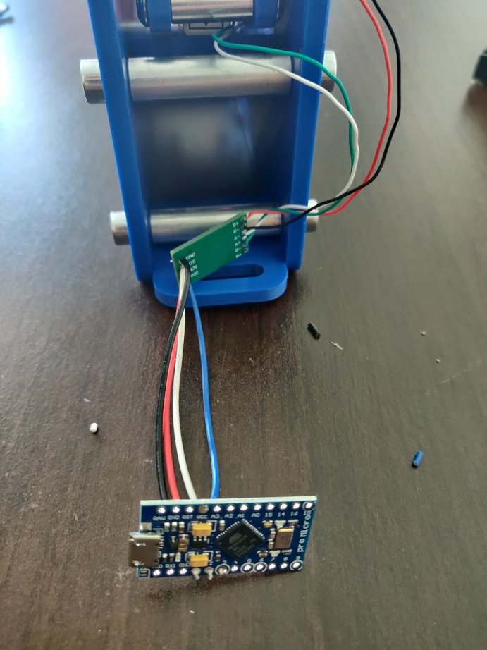
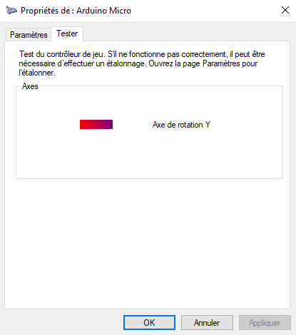
And that’s all 🙂 ! All you have to do is connect your Arduino board to your PC and apply the Arduino sketch. You must use the Windows game controller to test the loadcell.
Recurring problems and their solutions
First of all, I invite you to carefully check your soldering, as well as the installation of the Joystick and HX711 libraries.
Issue : I got an error message when compiling my sketch.
Solution :
- Use another USB cable (a data transfer cable)
- Change the USB port
- Connect the USB board directly to the PC
- Make sure you have chosen the right PORT and the right Board in the Arduino software (“Tools” menu ).
Issue : My loadcell pressure is reversed
Solution :
Edit the line n°32 of the Handbrake Arduino sketch, you need to remove the – just before scale
Issue : I have a dead zone when pressing my loadcell
Solution :
Slightly adjust the tightness of the four M4 and M5 lock nuts which support the loadcell.
If everything is OK, you must now fix the two boards (Arduino and HX711) inside your fixed part. You can use glue or good tape.
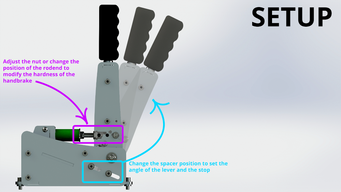
STEP 6 : Adjusting your Handbrake
You can easily adjust the hardness, stop and angle of your handbrake. It’s up to you to find what suits you best. 😉
Congratulations ! Your DIY Sim Racing Handbrake is complete, you can now enjoy it in your favorite games.
The CAD files are available in the shop: https://www.diysimstudio.com/produit/diy-sim-racing-handbrake/
If you have any questions or issues while making this Handbrake, you can post in the comment section, I will help you as soon as possible.

